Support OPC Server

Overview: Optimize OPC, OPC with Wonderware, PLC program content changes, OPC Classic to OPC UA, OPC DA Core Components, OPC Tunnel, OPC and Excel, OPC UA station search, OPC UA many server conections, OPC UA alarm, OPC UA reverse connections, OPC to Siemens S7 200, OPC to Siemens Logo, Handle PLC variables over MQTT, MQTT 5 and variable types, OPC to Mitsubishi Melsec Q, OPC to Mitsubishi FX5, Modbus Server, BACnet alarm requirements.
Answer:
Often the reason are a lot of long fields or error texts or recepture fields. This things are needed in the SCADA software only if the error or field condition changes. Normally this is true if the error index is changing. The SCADA software is registering the ling text for changing, a standard OPC server polls the long data for changes. Registering the data after the condition is changing will be too slowly also. This results in a heavily network load.
The solution for this: Define under "tables" "Wizard long data" a new optimizing. Call it "Error texts". Select the error index in group 1. In group 2 choose the long error text. The alias name which redirects the existing OPC item to the optimized element is created automatically.
Answer:
Please use this documentation. It can be found in the download area and in the manuals also.
Answer:
The OPC Server checks each ten seconds for
changes in the controller. If a change is detected it reorganizes
internally all necessary things. But it is preferred not to write into the
controller if the controller data elements are changed frequently. Reading data is secure always.
The PLC program change counter can be used from OPC applications over the System topic.
Answer:
Yes. Please create in the Tani OPC server a connection to Your OPC UA device. In Your OPC DA client You will reach Your device normal with browsing: Tani OPC server, next is the connection to Your device. The rest works as normal as in other browsing.
Answer:
For reinitializing or removing of the OPC Core Components it is important that no software ist using them. This is handled by the batch file "OpcUr.cmd". The file should be copied to c:\Windows\SysWOW64. Please open a command prompt as administrator. Change into the directory with cd c:\Windows\SysWOW64 . The file knows a command line parameter -r which unregisters the components and registers them again, no files are removed with this parameter set. Some dialogs are shown, confirm them please. There may happen errors if the files are in use. A reboot of the computer may solve this. If not please stop the program which is using the components and remove the affected files by hand. After this for security issues it is recommended rebooting the computer again. A new installation of the Tani OPC Server or the PLC Engine Collect will reinstall and reinitialize the OPC Core Components correctly. All OPC DA software of other manufacturers will work again also. All effects with the OPC DA components with access privileges now are fixed.
Answer:
With the OPC tunnel which is a build in feature in all Tani OPC servers. The faster OPC protocol for this is OpcPipe, you can use OPC-UA also.
Answer:
Please use this example.
Answer:
Under Windows the Bonjour service version 2.0 need to be installed, additionally the UDP port 5353 need to be opened in the firewall.
Under Linux the avahi daemon need to be present. You will find it in the packet manager of your distribution.
The UDP port 5353 need to be opened in the firewall.
Please do not install multiple OPC UA discovery servers on the same machine.
If you try using an external discovery server mostly the certificates need to be proved.
Ask the discovery servers manufacturer for details.
Answer:
Most OPC UA clinets are using this sheme for the connection establishing:
This is neccessary because needed connection details are available after the first short connection only. This is a design flaw in OPC UA, this can be fixed with an new OPC UA protocol only.
The Tani OPC server needs some millisecond for the "first" connection shutting down. So depending on the system behaviour more than the
So more than the real OPC UA connections will run at a short time. If the limit configured in the OPC UA server connection is reached the
station denies the IP connection request. The client then breaks up any further connection request for a long time.
Best is configuring some more OPC UA server connections as needed for the number of partners. Good is 10% more connections.
Answer:
The Tani OPC UA alarm and conditions are working as in the OPC UA specification talks about. Additionally all variables reflecting the alarms and conditions are offered in the variables tree all OPC programs can browse.
Create the alarm with XML file
The example XML file contains a "Test-Alarm" of type ExclusiveLevelAlarmType (in folder Objects/Tani-Example). To configure it, the following properties must be written:
Finally enable the alarm:
To monitor the alarm:
To create more alarms, use one of these methods:
Answer:
OPC UA supports connections for reaching an OPC UA server which is behind NAT as an example. In this cases the UA server initializes the network connection to the client.
The necessary configuration settings are shown i the "Expert settings" choosen in the OPC UA Settings of the connection
On the UA Server set the checkmark "Reverse Connect". Enter the IP address of the client machine in the reverse connection part. Mostly let the "Endpoint URL" IP address as 0.0.0.0
On the UA client side also set the checkmark "Reverse Connect". Enter the IP address of the server machine in the reverse connection part. Mostly let the "Endpoint URL" IP address as 0.0.0.0
Do not use a IP port which is handled by any other connection of the client or the server nachine.
Answer:
Please use this example. One data block only exists, it has the number 1.
Answer:
The Siemens Logo works as a Siemens S7 300 compatible. Mostly the automatically TSAP search will find this PLC, but if the TSAP is edited in the PLC it need to be entered manually.
Answer:
Two ways are existing:Configure a MQTT broker with the "Enable the $topics/" functionality.
In your MQTT client for accessing the variable Memory.TestInteger register
"$topics/Memory/TestIngeger". Using the status variable functionality in the graphical
OPC Server configuration needs "MyMQTTclientConectionName.$topics/Memory/TestIngeger" as item name
Ideally the requests are using JSON. So set the "JSON data format" setting in the configured broker.
Then the data will received in your client including the variable, the data value and the data type.
This also can be used for structured variables.
The variable comes on data changes.
Variables can be written also.
Limit the access using the access levels.
Offer the variables assigning symbols to the MQTT connection using a specific item syntax.
An example is
MyVariable{{Int 32}}
for a reading 32 bit signed variable. Reading structured data follow this example:
MyStructuredVariable{{Structure:MyStructure}}
Using structure mostly needs JSON or XML choosen ion the data format of the MQTT connection.
Create a MQTT client or server (broker) connection
Assign PLC variables to this connection.
Now the defined variables can be read over MQTT.
If MQTT needs sending variables on a trigger condition as a value change a logic table is required.
Logic tables are included in the PLC Engine and OpcEngine products.
Answer:
Offer the variables using the datatype names as
Boolean, SByte, Byte, Int16, UInt16, Int32, UInt32, Int64, UInt64, String, Float, Double, DateTime.
Optional modifiers are
BigEndian, LittleEndian, Array,
BitArrayLength1, BitArrayLength2, BitArrayLengt31 ,BitArrayLength4, BitArrayLength5, BitArrayLength6, BitArrayLength7.
The defines item syntax used in symbolic variables - example is MyVariable{{Int 32}} - will be converted to the datatype names above.
Create a MQTT client or server (broker) connection, choose MQTT 5.
Assign PLC variables to this connection.
Answer:
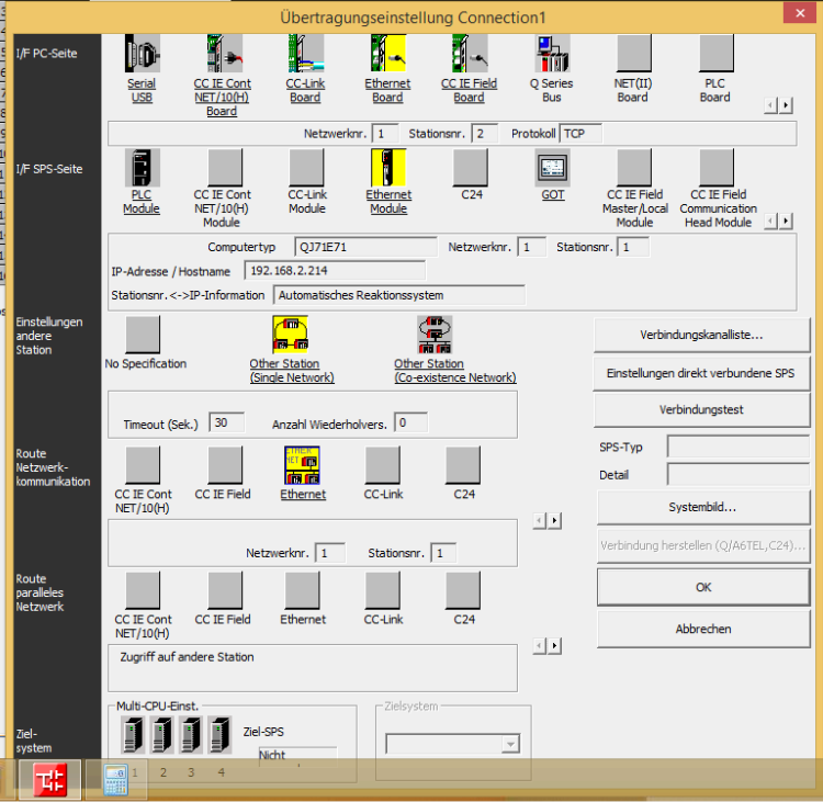
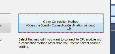
This images are showing the settings for the OPC server and the PLC (the IP address need to be used from your real plant network)
![]()


Answer:
This images are showing the settings for the OPC server and the PLC (the IP address need to be used from your real plant network)


Doubleclick on the PLC Module icon. 


Answer:
Create a Modbus server with "New Connection", "Data Server", "PLC Emulation".
Choose "Modbus", choose the port of the server.
Choose the Modbus node address. If multiple nodes are needed enable Emulate Multiple Slaves.
Define the areas to emulate and the amount of elements in an area. If multilpe nodes are enabled each node offers the elements separately.
Use the item syntax directly or define symbols in the Modbus server connection. The documentation for the item syntax is in the
graphical configuration or in tn manuals area Item Syntax.
An example for a multi node server is id5.r100. This accesses Modbus register 100 in the node 5 emulation.
Answer:
In the BACnet device